
Skip to content

PLANNING SUN

Business

Auto Tape Mounter

Auto Tape Mounter

SEMICONDUCTOR AUTOMATION

Auto Tape Mounter

BACK GRIND TAPE

SEMICONDUCTOR AUTOMATION

Auto Tape Mounter

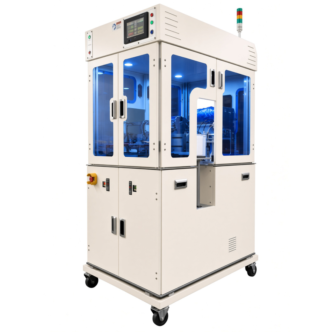
Full-auto equipment that automatically attaches blue tape to wafers for the B/Grind process, maintaining productivity and stable quality.
Full Auto · 6″ Wafer Dedicated · Automatic Blue Tape Attachment
Auto Tape Mounter

EQUIPMENT CONFIGURATION

Equipment Configuration

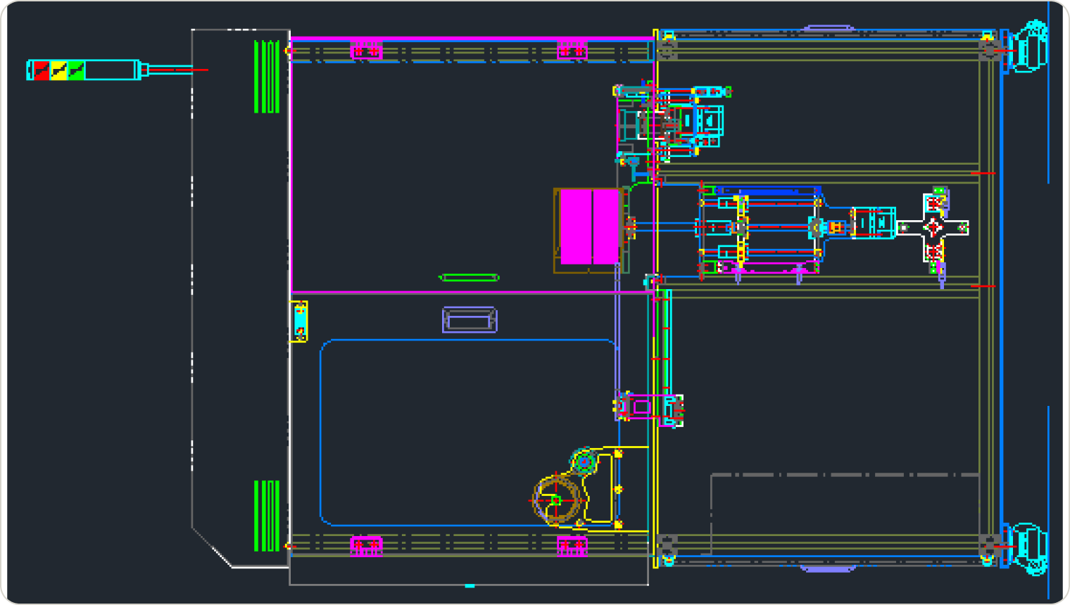
Configured with five core units from Main Frame to Tape Loading & Rolling Unit.
Auto Tape Mounter equipment layout

CORE UNITS

  1. 01Main Frame & Control Panel 外
  2. 02Mounter Chuck Sliding Unit
  3. 03Wafer Elevator Unit
  4. 04Tape Cutting Unit
  5. 05Tape Loading & Rolling Unit

EQUIPMENT OPERATION SEQUENCE

Equipment Operation Sequence

A 10-step process from wafer input to carrier magazine output.
  1. 01

    WAFER INPUT

    Wafer Input

  2. 02

    EDGE DETECTION

    Wafer Edge Detection

  3. 03

    WAFER ROTATION

    Wafer Rotation

  4. 04

    D-CUT ALIGN

    D-Cut Alignment

  5. 05

    WAFER FLIP

    Wafer Flip

  6. 06

    WAFER CHUCK

    Wafer Chuck Placement

  7. 07

    TAPE LAMINATING

    Tape Laminating

  8. 08

    TAPE CUTTING

    Tape Cutting

  9. 09

    TAPE RECOVERY

    Remaining Tape Recovery · Chuck Home Return

  10. 10

    MAGAZINE OUT

    Carrier Magazine Output

OPERATION METHODS

Operation Methods

Operates through two core processes from wafer supply/alignment to tape laminating and finished product output.
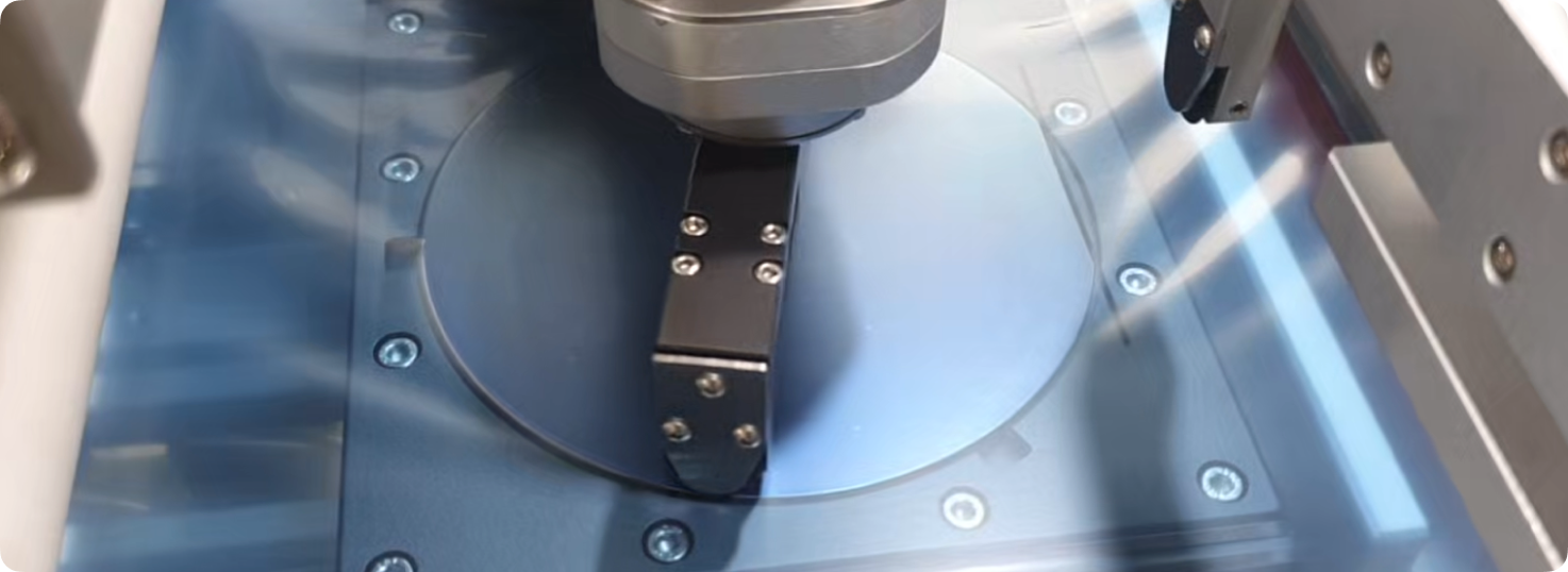
WAFER SUPPLY

WAFER SUPPLY

A wafer loaded through the elevator and pusher is moved to the mounter chuck after its D-cut position is recognized by the alignment and rotation units. The alignment position is determined by a BLDC Motor 30W and fiber sensor, then transferred to the chuck by the vacuum unit and vacuum pad. The magazine elevator consists of a BLDC Motor 30W and ball screw.
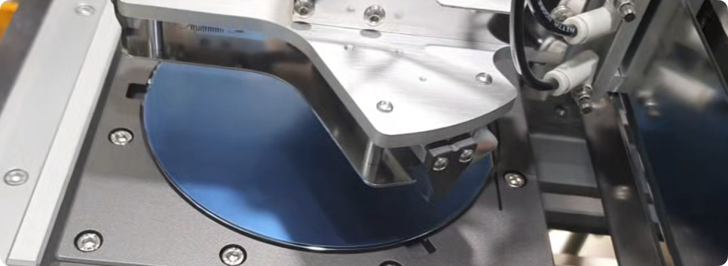
TAPE & ROLLING

TAPE & ROLLING

The mounter chuck moves through an electric unit, and laminating is performed as the tape roller descends. The chuck moves and returns through the LM guide and ball screw, and the completed product is loaded into the out magazine.

TECHNICAL SPECIFICATIONS

Main Specifications

Equipment size, applicable wafer, power/air supply, control, and major component specifications.
Model
P-ST X2 GMF
Equipment Size
825(W) × 1100(D) × 1750(H) mm (Tower lamp excluded)
Input Power
Single-phase 220 VAC ±10% / 50/60 Hz
Supplied Air Pressure
5 bar
Applicable Wafer Size
6″ dedicated
Electrical Operation
M2i 7″ Touch Panel
Electrical Main
LG PLC / XBC-DN32H
Motor
LS Servo Motor 400W BLDC Motor 50W / 30W 外
Electrical Components & Others
Fiber Sensor / Autonics
Pneumatic Device
SMC & TPC

※ Actual manufacturing specifications may change depending on customer consultation and applicable process conditions.

MEDIA & RESOURCES

Equipment Video and Technical Materials

Check the actual equipment operation video and product manual.
EQUIPMENT VIDEOWatch Equipment Operation Video

PRODUCT MANUAL

Request Equipment Manual

Request the manual for delivery by email after review.

PROJECT CONSULTATION

Considering Back Grind Tape Mounter adoption?

We propose the optimal automation configuration based on wafer specifications and production conditions.
Equipment Adoption Inquiry