Skip to content

PLANNING SUN

Business

Auto UV Irradiation System

Auto UV Irradiation System

SEMICONDUCTOR AUTOMATION ·

Auto UV Irradiation System

AUTO UV IRRADIATION SYSTEM

SEMICONDUCTOR AUTOMATION · 05

Auto UV Irradiation System

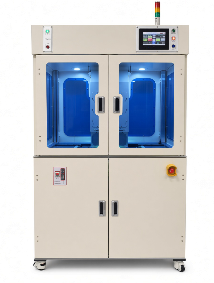
This equipment performs product input/output and UV lamp irradiation in full-auto mode so UV tape can be easily separated from the wafer surface. It is designed to control irradiation dose by product and maintain productivity and stable quality.
Full Auto · 6-inch Dedicated · Product-Specific UV Dose Control · External UV Exposure Prevention
Auto UV Irradiation System

EQUIPMENT CONFIGURATION

Equipment Configuration

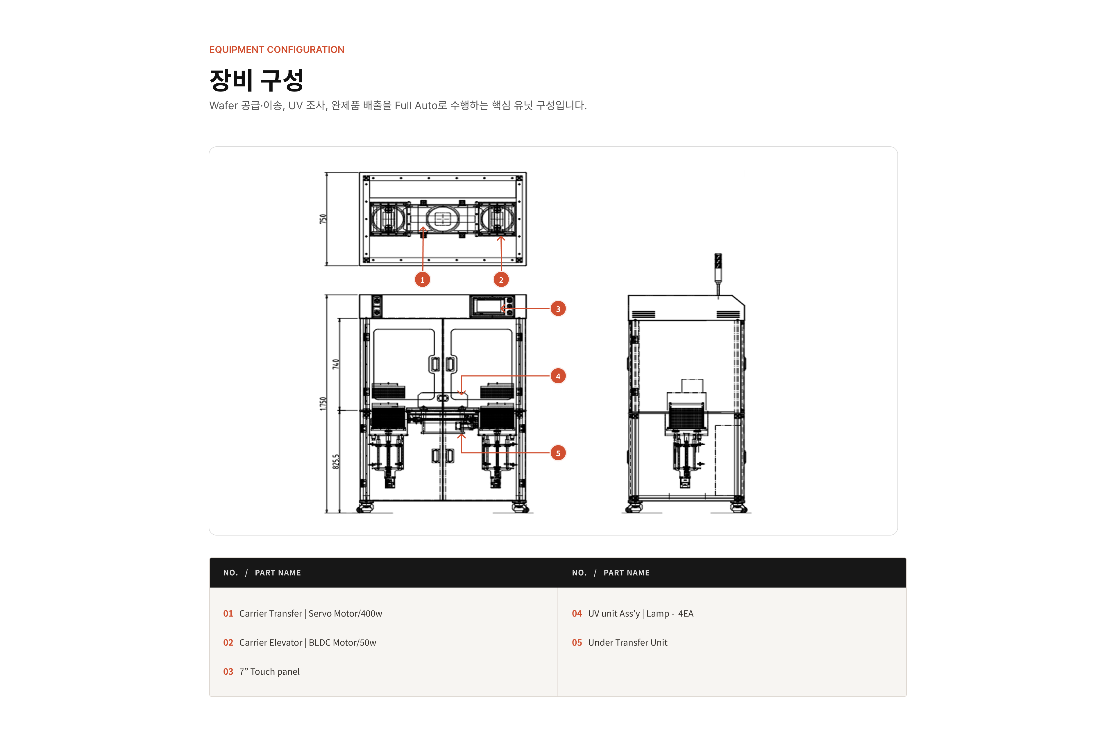
Core unit configuration that performs wafer supply/transfer, UV irradiation, and finished product output in full-auto mode.
Auto UV Irradiation System equipment layout
NO.   /   PART NAMENO.   /   PART NAME

01Carrier Transfer | Servo Motor/400w

02Carrier Elevator | BLDC Motor/50w

037” Touch panel

04UV unit Ass’y | Lamp - 4EA

05Under Transfer Unit

AUTOMATED PROCESS

Equipment Operation Sequence

12-step full-auto process from UV system start-up to finished cassette output
  1. 01

    UV SYSTEM ON

    UV System Power ON

  2. 02

    LAMP CHECK

    Check Normal UV Lamp Operation

  3. 03

    WAFER INPUT

    Wafer Input

  4. 04

    EDGE DETECTION

    Wafer Edge Detection

  5. 05

    WAFER LOADING

    Automatic Wafer Transfer

  6. 06

    POSITIONING

    Positioning in UV Irradiation Area

  7. 07

    UV IRRADIATION

    Product-Specific UV Irradiation

  8. 08

    DOSE ADJUSTMENT

    UV Dose Condition Adjustment

  9. 09

    RECIPE STORAGE

    Save Product-Specific UV Irradiation Time

  10. 10

    AUTO IRRADIATION

    Automatic UV Irradiation

  11. 11

    UV COMPLETE

    UV Irradiation Complete

  12. 12

    CASSETTE OUTPUT

    Finished Product Alignment and Cassette Output

OPERATION METHOD

Operation Method

Continuously controls wafer supply, D-cut alignment, UV irradiation, finished product output, and safety/thermal management functions.
WAFER SUPPLY & D-CUT ALIGN

WAFER SUPPLY & D-CUT ALIGN

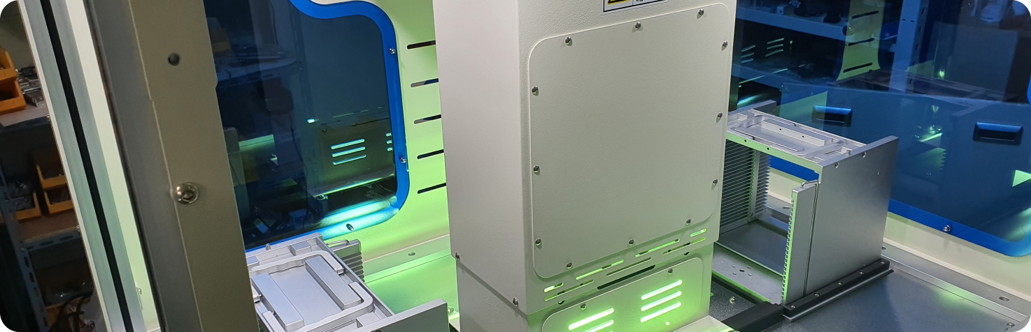
The wafer is loaded by the elevator and pusher, and after the alignment/rotation unit recognizes the D-cut position, it is transferred to the mounter chuck.
UV IRRADIATION CONTROL

UV IRRADIATION CONTROL

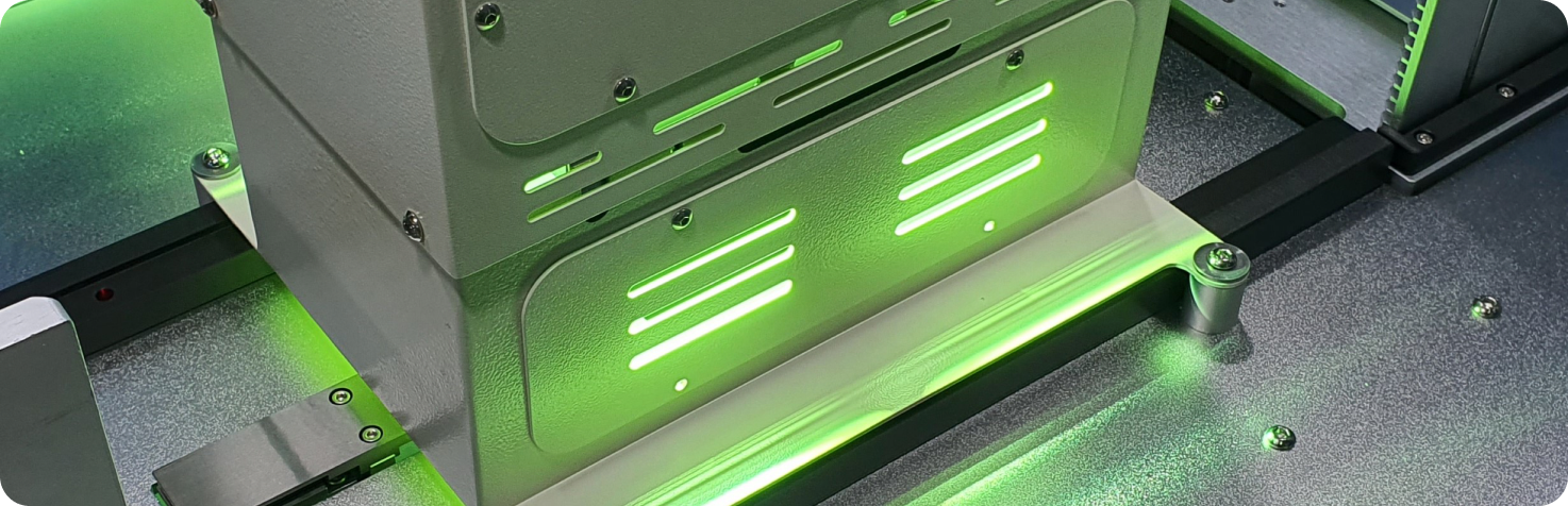
After seating the wafer in the irradiation area, product-specific UV irradiation is performed. Irradiation dose and time are adjusted and managed according to product conditions.

FINISHED PRODUCT ALIGNMENT

FINISHED PRODUCT ALIGNMENT

The wafer after UV irradiation is aligned in the cassette, loaded step by step, and discharged stably.

SAFETY & THERMAL MANAGEMENT

SAFETY & THERMAL MANAGEMENT

The UV lamp is shielded to prevent direct external exposure, internal fans dissipate heat, and product damage during operation is prevented.

TECHNICAL SPECIFICATIONS

Specifications and Main Components

Equipment type and size, control/drive, major components, and operating conditions
Model
P-ST X2 AUF
Equipment Size
1080(W) × 750(D) × 1750(H) mm (Tower lamp excluded)
Input Power
Single-phase 220 VAC ±10% / 50/60 Hz
Applicable Wafer Size
6-inch dedicated
Electrical Operation
M2i 7 inch Touch Panel
Electrical Main
LG PLC / XBC-DN32H
Motor
LS Servo Motor 400W / BLDC Motor 50W / 30W etc.
Frame and Cover
Steel tube frame and powder coating
Electrical Components & Others
Fiber Sensor / Autonics
Pneumatic Device
SMC & TPC

※ Detailed specifications may change depending on the applicable process and customer consultation conditions.

TECHNICAL DOWNLOAD

Equipment Manual and Technical Materials

Download the manual to check equipment specifications and operating information.

PRODUCT MANUAL

Request Equipment Manual

Request the manual for delivery by email after review.

PROJECT CONSULTATION

Considering Auto UV Irradiation System adoption?

We propose the optimal automation configuration based on process conditions and production goals.
Equipment Adoption Inquiry